
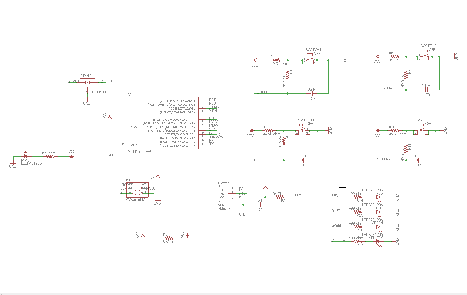
The main assignment for this week was to make a simple board, by adding to the given design just a LED and a switch. but I decided to play a little. The purpose of this board is to play a game of simon says, it has 4 leds and 4 buttons. Idea is that it gives you a random series of lights that the user then must replicate by pressing the buttons.
I chose to use eagle for designing my boards because it is pretty much an industry standard, and with Autodesk's support it has good long future ahead.

Adding components is simple in eagle, but it makes things easier that once you have designed a functional thing, like the circuit for a button, you save it as a design block, that you can then just drag and drop to future schematics where needed.
Things get more complicated when you need to make your own components for use in eagle. some component might be close but not enough to be usable as it is, and you need to make your own variant to be used later. So it is an idea to start your own library file where you store your own designs.
One thing that is making life much easier with eagle, is that you can change the save file locations so that you can toss everything into a cloud, then have all your eagle clients point to that locations. This way all your work is saved in the cloud and is accessible on all your computers, including the library you made and the design blocks.

Simon Says traces

Simon Says border

Simon says BOM

Simon Says placing

Well that didnt work out the way I planned, the ATTiny44 chip has way too little memory for this purpose. Also when I designed this board I was under the illusion, that the pins for the ISP programming were dedicated pins that could not be used for anything else. Later experience has proven me wrong, altough it can look amusing as the board looks like it is glitching when it is being programmed.
Would be an idea, that later on I take the ATTiny841 chip and experiment with it, if the board I wanted to make is possible to make with its capacities.
To make sure connecting both the button and the LEDs worked, I did run a few simulations, and altough I understood little of it, they did indicate that it might be possible to use them in the same pin. Taking the advantage of the pin's ability to bounce between input and output faster than human can see or react. While it did work, it did have its limitations, that can be worked around by utilizing the programming pins as well, not to mention ATTiny841 has 12 ADC pins, where the normal ATTiny44 has only 7.
For my second project for this week I also made me an FTDI board. As the proper FTDI cables are a finite resource, I figured I would make my own board, that let me use a dime a dozen USB cable. I will cover the board more extensively in its own page
Initially when we started to make our own boards, Jari of our group who has experience with circuit boards, made an initial Design Rule file for us to use with the roland mill. I have later on finetuned my own version of it. Instead of sticking to 0.4mm spacing I have reduced it to 0.3mm. This was possible thanks to the 0.1mm milling bits I bought for myself, they have a 45 degree angle in the tip, meaning the actual cutting width at 0.1mm depth is exactly 0.2mm. This lets me use the 0.3mm widths as it gives me two clean passes to make the traces, and with this width I can pull two neat lines under the resistors. Since the milling bits are quite inexpensive, I got 10 for under than 20 dollars, it would be an idea to include them in the lab inventory.
The paperwork
- Assesment
- Have you, Shown your process using words/images/screenshots?
- Have you, Explained problems and how you fixed them, including how you worked with design rules for milling (DRC in EagleCad and KiCad)?
- Have you, Included original design files (Eagle, KiCad, Inkscape, .cad - whatever)?
- Lecture Details
- Lecture Video
- Review Video
- The Files
Sub-pages
-
 Simon Says
The main assignment, fully soldered.
-
 FTDI interface 5v/3,3v
Additional project, FTDI interface board.
-
 Eagle guide
Instructions to using Eagle
-
 Board manufacturing guide
Instructions to preparing the files for milling.